Hello friends,
On my journey to learn more about circuits I wanted to start as small as I could imagine. While yes I can handle a lot of logic directly with code I feel as if that won't teach me fully. That is why I decided to work towards solving a challenge in the most basic way I can imagine.
The Challenge
The challenge is as follows: Given two buttons connected to one button, create a circuit that allows only the first pressed to light the LED. After a winner LED is turned on, the buttons should stop working.
It's a fairly simple task but I really had to spend some time figuring out some basics. Namely, logic gates.
Logic Gates
So what are logic gates. Logic gates are the building blocks of digital electronics and computers. They allow you to control the flow of electricity in useful ways. The gates are as follows.
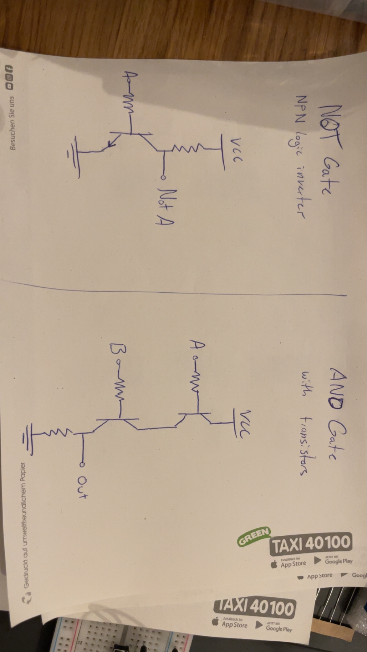
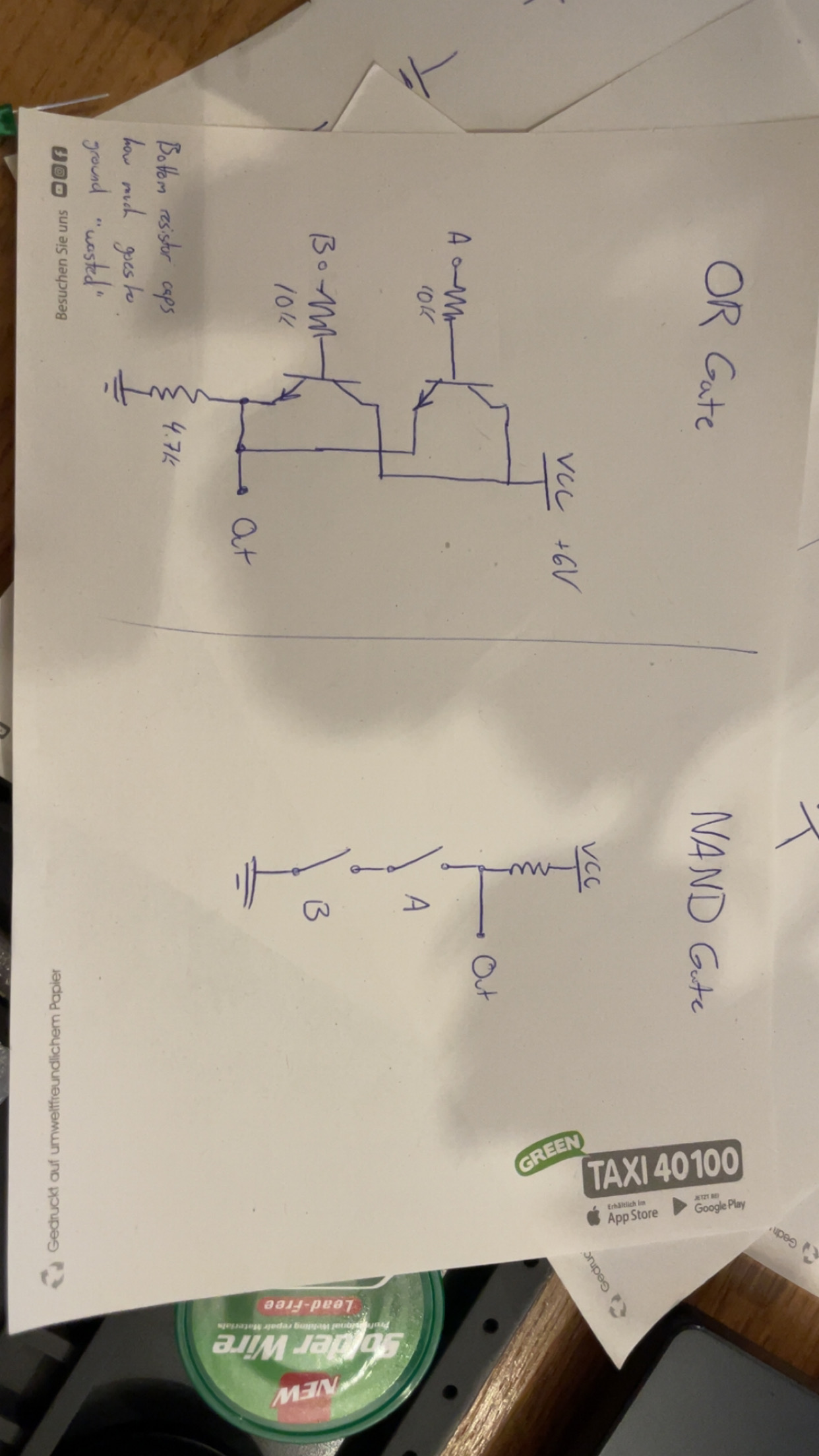
AND, OR, XOR, NAND, NOR, XNOR, as well as a NOT gate.
An AND gate for example will only have an output of 1 if both inputs are 1. On the other hand OR will turn on as long as one or both inputs are 1.
After learning about the gates, I spent today writing them down as diagrams, and then trying to create them on a breadboard just from drawing. I think it's good practice to be able to read and create these schematics to continue in this field.